12" f/4 Newtonian
This telescope was originally purchased from and branded 'Bintel' but it's manufactured by GSO and sold under different names around the world - the most common being AT12IN.
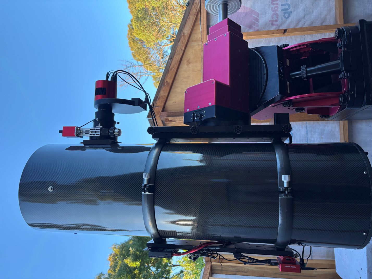
This is the telescope I use the most. It's 'fast' and produces nice stars without any visible chromatic aberration. After many modifications, this is how the scope looks now when it's set up and ready for a night's imaging. I could not be happier with the current setup and performance.
Specifications
| Type | Newtonian |
| Aperture | 304.8mm |
| Focal Length | 1200mm |
| F-ratio | f/4 |
| Diagonal Mirror Obstruction | 87mm (29%) |
Weight Breakdown
| Rings and Dovetail | 2.7 kg |
| Focuser + Adaptors | 1.0 kg |
| Secondary & Assembly | 0.6 kg |
| Mirror Cell Assembly | 2.1 kg |
| Primary Mirror | 6.3 kg |
| OTA | 7.3 kg |
| Total | ~20 kg |
Upgrades
I have performed the following upgrades on this scope:
- Carbon fibre OTA: Replaced the steel OTA tube with a carbon fibre tube from Klaus Helmerichs. The new tube is much stronger and has greatly reduced the movement at the base of the focuser.
- TS-Optics 3" Focuser: Replaced the focuser with a TS-Optics 3" UNCN3. The original focuser ended up breaking - it was not up to the job.
- 3" Wynne Corrector: Added 3" Wynne Corrector 0.95x 3KORRW from ASA.
- ZWO EAF: Added a ZWO EAF to automate focusing.
- 4" Secondary Mirror: Replaced the secondary with a larger 4" 1/30 Wave PV from Antares Optics.
- Custom adaptor: A custom adaptor from Joshua Bunn at Southern Cross Custom Engineering to connect the ASA Coma corrector to the ASI2600MM Camera M54 thread.
- Extended dovetail: Replaced the dovetail with a longer one for better balance.
- Upgraded fan: Replaced the fan with a larger one for better cooling.
- Catseye Hotspot: Changed the primary mirror center spot with a Catseye yellow Hotspot.
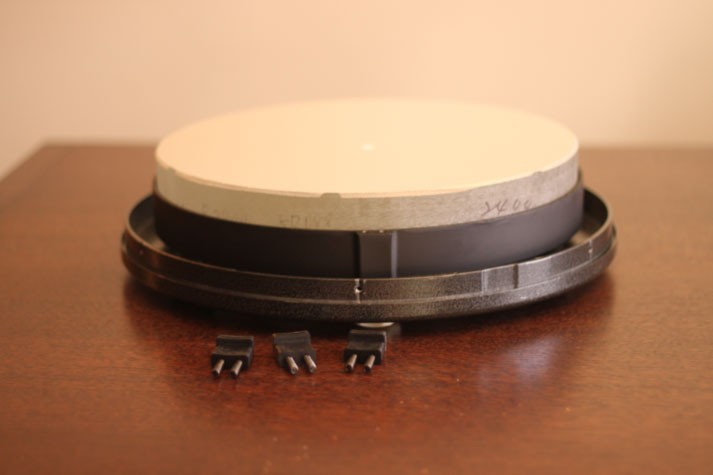
Primary Mirror
The mirror is approximately 37mm thick and was already center spotted reasonably accurately. The primary mirror rests on 3 triangles that make up a 9-point cell. Only one corner of each triangle is attached to the mirror with adhesive tape. The other two corners are free to move. Each triangle is made of metal reinforced plastic and has a plastic socket moulded on the back. This socket snaps onto a ball which is attached to the cell by a captive thread. This arrangement allows the triangle to tilt and evenly distribute the weight of the mirror.
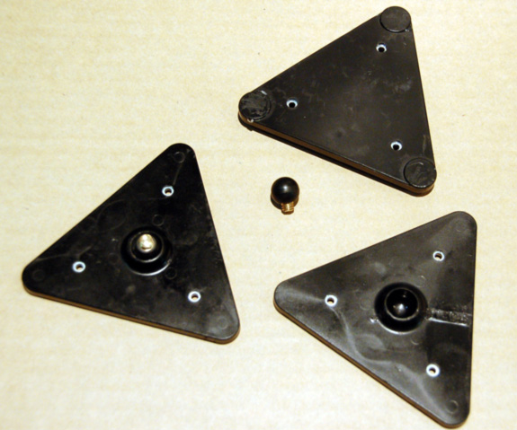
9-point mirror support triangles
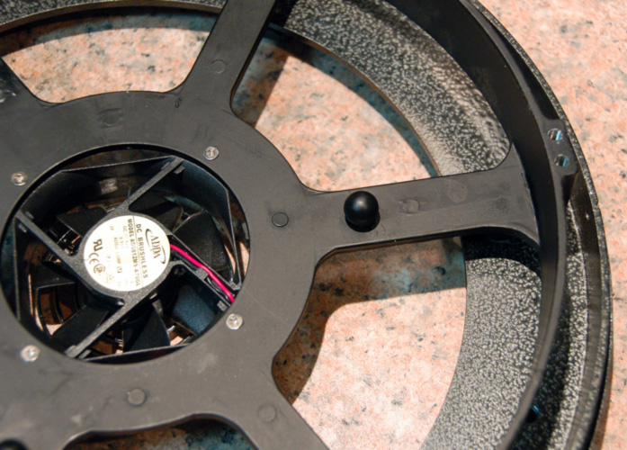
Mirror cell assembly
There are 3 standard GSO style rubber mirror clips. These should be checked to make sure they are not touching the mirror (I have removed them in the image below).
The cell has 3 push and 3 pull screws spaced evenly 60 degrees apart. It works but could be better - the cell can easily be bent by over-tightening the push screws. This is annoying but doesn't affect the optical performance; it just makes the collimation action more 'spongy' and less precise.
Finally, there is a small 12V fan which blows cool air onto the mirror.
Secondary Mirror
The secondary is held in place by a GSO standard plastic holder. The four spider vanes are about 1.5 mm thick and are susceptible to bending when the spider is removed from the OTA. The secondary mirror is 87 mm x 123 mm and appears to be offset by about 5 mm away from the focuser (you should be able to see the offset in the image below).
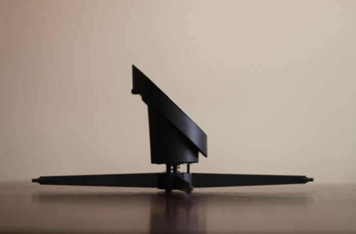
Using this calculator, the required diagonal offset is 5.56mm which is within the error margin of the measured value. The secondary is undersized and doesn't even provide 100% illumination at the centre of the image. Whilst this is not a big problem, I have replaced my secondary with a larger one (4 inch) from Antares Optics. The new secondary mirror is 4.0 inches 1/30 wave PV.
OTA (Optical Tube Assembly)
The original OTA was constructed of 0.74 mm thick sheet steel, is 1150mm long and 357mm in diameter. The outside is powder coated white and the inside is matt black paint. Reflections can be seen when looking down the OTA.
At night, the top of the OTA is usually about 2 degrees cooler than the underside. For detailed thermal imaging analysis showing temperature distribution across the primary mirror, secondary mirror, and OTA components, see the thermal camera images taken with a Fluke Ti25 IR Fusion Thermal Imager.
In my experience, the OTA does flex around the base of the focuser. At first I reinforced it with a bar of 3mm aluminium. The following video was made AFTER the OTA was reinforced. By hanging the camera (2.3 kg) off the focuser, and simultaneously looking through a Catseye Infinity XLK, the shift in collimation can be clearly seen by observing movement of the centre spot reflections. This is a highly sensitive test and can be used to check if the focuser or tube is sagging.
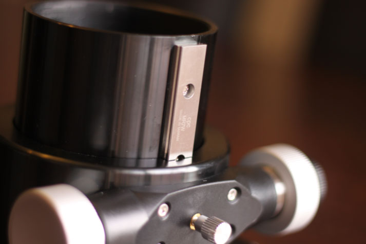
Focuser
The original focuser was based on a linear bearing. Although smooth, it struggled with heavy loads especially when the orientation needed to lift the camera vertically. Tightening the tension knob (image below) eventually broke the plastic housing.
I have replaced the focuser with a TS-Optics 3" UNCN3 Crayford focuser with a ZWO EAF robotic focus motor. This focuser has a dual speed mechanism (10:1 reduction) and copes well with the weight of the camera and coma corrector. This is one of the few focusers that are large enough for a 3" coma corrector.

Coma Corrector
I have coupled this scope with a 3" Wynne Corrector 0.95x 3KORRW from ASA. It's the perfect size to fit in the stock focuser. This annotated image shows the 3 inch coma corrector and SBIG STL Camera in place. The first test image taken with the combination can be seen here.

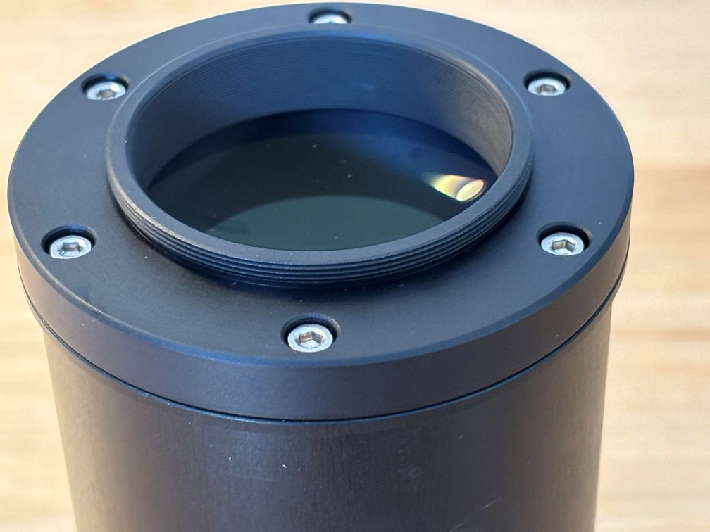
ASA Coma corrector and custom adaptor