GSO 8 RC Collimation
Out of the box with no adjustments on my part, the collimation looked like this. Unfortunately this was taken in a rush between clouds and the focus and tracking are not very good.
Up until now I felt I was continually chasing my tail – adjusting the secondary would not reduce the elongation of off axis stars. Adjustments to the primary when the secondary was poorly aligned made the situation worse, occasionally leading to a 'runaway' situation where adjustments intended to improve on axis performance severely impacted off axis performance – quickly leading to a gross miscollimation situation.
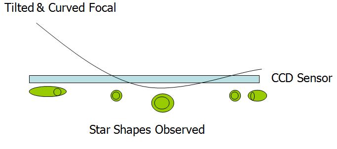
The situation is compounded by the difficulty to interpret images taken with a miscollimated scope. The star shapes produced by a tilted & curved focal plane intersecting a flat imaging plane are very complex indeed. Stars can be in focus at 2 different points and at varying degrees of out of focusedness across a CCD image. Very confusing and not a nice image to look at. Many of the recent uncropped RC images you see on the internet taken with large sensors exhibit this problem (including my own early attempts).
After much experimenting, I have found what I believe is a reliable way to collimate my GSO RC. From my tests it seems to converge towards good collimation, and does not lead to runaway miscollimation. It's based on:
- The Canon EOS Liveview feature
- A Bahtinov Mask to check off axis defocus
Key advantages
- Long exposures & autoguiding not required
- Immediate feedback on all adjustments
- Easy to work out which screw to turn and which direction to turn it
This procedure only addresses the adjustment of the secondary adjustment screws at the front of the scope and the primary push/pull screws at the back of the scope. Other adjustments, such as centering the spider veins, adjusting the distance between the primary and secondary mirrors, adjusting the tilt of the focuser relative to the primary are not covered.
The key steps are as follows:
- Align the secondary using a bright, centered defocused star and live view.
- Align the primary & focuser tilt with a Bahtinov mask and a bright off axis star
- Repeat until perfect, always finishing with step 1.
In this scope the focuser, primary mirror and primary baffle tube move as one unit and can be adjusted using the screws on the rear of the OTA. The scope is often said to have a fixed primary - in fact the primary mirror is fixed to the focuser, not the back plate of the OTA. Therefore it is not possible to adjust the tilt of the focuser independently of the primary. In my case, this is not necessary to get good collimation - it is already square enough as delivered.
Details
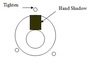
1. Place a bright star at the dead center of the field of view. Defocus the star using live view by racking OUT the focuser. (If you rack the focuser IN the instructions need to be reversed and I have also found the rings are harder to view) Place your hand in front of the scope to cast a shadow over the 'fat' side of the rings. This is will help you find the correct screw to tighten.
Rule to remember:
TIGHTEN the screw closest to your hand when it is over the fat section of the defocused star.
Alternatively screws on the opposite side should be loosened. Adjust the 3 secondary screws such that the doughnut and rings are concentric. Move the focus in and out while watching the rings to check they stay concentric. Don't waste time on this early on. This does not have to be perfect on the first iteration - it only needs to be perfect on the LAST iteration.
This video shows what it looks like in Liveview. At this point the scope is out of collimation and you can see my hand reach across the 'fat' part of the ring, so I tighten the screw near my hand.
CCD Inspector has a single defocused star collimation function you can use to collimate the secondary.
From my experience, it's actually faster and easier to use Liveview and the results are better and less affected by seeing.
3. Now place a Bahtinov Mask over the scope and make perfect focus, again on a star at the exact center of the field of view. Use the hand controller to move the star to each corner of the image and carefully observe the focus using the zoom function in Live View.
This video shows what it looks like in Liveview
In the image below, the star stays in perfect focus, except when it is viewed on the right side. It's normal for field curvature to cause stars at the edge to be defocused, but all 4 corners should have the same amount of defocus. If the image plane is tilted, stars on one side (or corner) will be further out of focus than the other side.
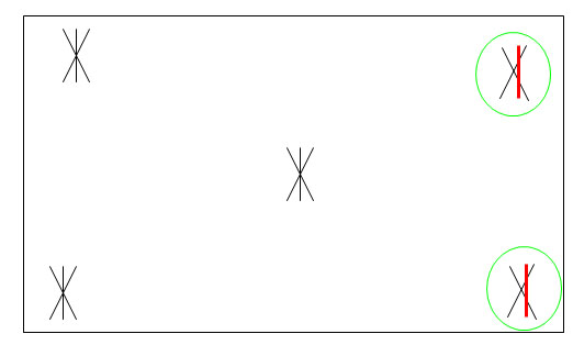
4. Rotate the mask 90 degrees at each corner when checking. The next movie shows why: a star might look in focus in one direction but not in the other. This will happen when there is tilt in X and no tilt in Y, for example
(new simpifed version below!)
5. Select which star (corner) that looks the worst. Use the 3 sets of push/pull screws on the back of the scope to move the star from the bad corner toward the center of the field of view. You may only need to move it about 1/3 of the way towards the center. If it moves in the wrong direction, turn the screw the other way. This is the beauty of this method - there is immediate feedback if you are adjusting in the wrong direction.
Remember when you are doing this that you are moving the focuser, camera and the entire primary mirror - there is a lot of weight involved. If you loosen the 'pull' screw, make sure you tighten the corresponding 'push' (locking) screw really well, otherwise collimation will be lost when you slew the scope.
6. The adjustments you made above will have destroyed the secondary collimation achieved in step 1. Therefore it's necessary to go back and repeat step 1 again. Keep iterating steps 1 and 5 until an equal amount of defocus is observed in all 4 corners.
I suggest to remove the tilt in the X axis only, then rotate the camera 90 degrees then start to work on the other axis.
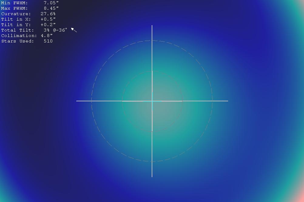
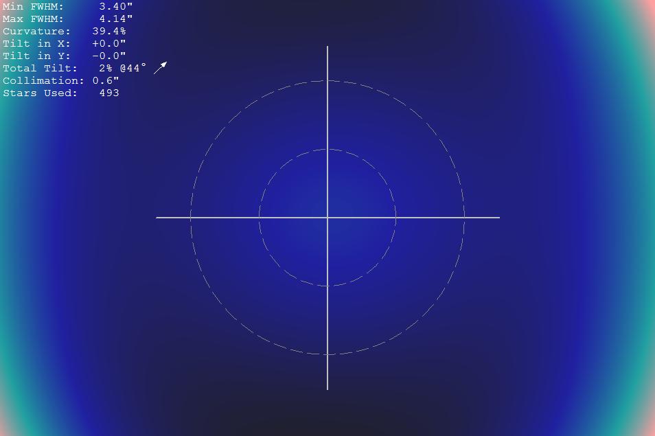
7. As a final check, use CCD inspector to measure the collimation and determine the direction and amount of tilt remaining. To do this properly takes some effort - you need to be autoguiding and take longer exposures. Be very careful because the results can be impacted if your tracking / auto guiding is not up to scratch or if you pick a bad target. I recommend to only use CCD Inspector to make very small adjustments (like 1/8 of a turn) to the secondary mirror only.
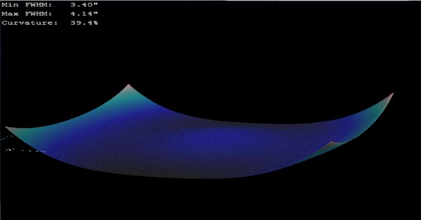
Results taken with a full frame Canon 500D, 5 min exposure guided on EQ6
(Notice that I focus on a star about 75% from the center to minimize curvature - that's why it's light blue in the first image, and a little raised in the second image.)
These are the 3 test images used to generate the above CCD Inspector results:
(Note there is a lot of flex in the system when these images were taken. I'll come back and update this page when that is resolved.)